Post by fastredponycar on Jul 30, 2008 20:28:43 GMT -5
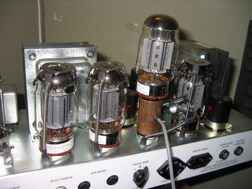
Ok so after a quick verification from Scott on this on exactly what is needed to be done and a few helpful tips from Matt, my Nitro is up and running with KT88's.
First thing is first.
You'll need obviously a pair or quartet of matched KT88 power tubes, a voltage meter, a large phillips head screwdriver or drill (to remove the amp from the head shell), a tiny precision flat head screwdriver, a soldering iron and solder, wire snips and last but not least, a 47K 1/2 watt resistor. I got a pack of 6 or so for a dollar at Radio Shack.
Optionally, you can also use a weber bias rite probe to take the guess work out of the biasing procedure. I have the single octal socket with the plate voltage/cathode voltage switch.
After you've got all your stuff, begin by removing the back panel of the amp and remove the 4 screws from the bottom and slide the amp out from the head shell.
First thing you want to do is fire up the soldering iron to get it hot while you prep the amp for surgery. I use the weller variable wattage unit from Sears as it lets me drop the voltage when working with more delicate pieces.
Next!
If you're using the weber probe, insert it into one of the inner 2 sockets and then put a KT88 into it and fill the rest of the sockets with the rest of the tubes. If you're only using 2 KT's just fill the center 2 sockets.

Now that your tubes are in, you can flip the amp upside down and let the side cleats on the inside of the headshell support the metal chassis while you work on it. The tubes should have enough room below to allow the amp to rest without them hitting the surface below. Just lower it slowly and carefully so as not to damage the tubes.
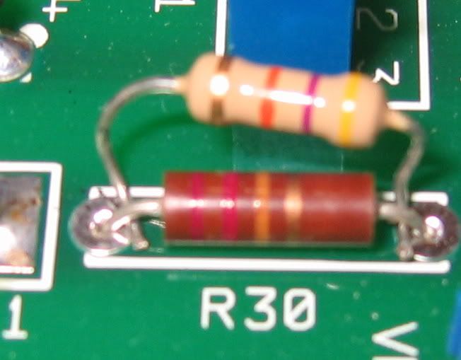
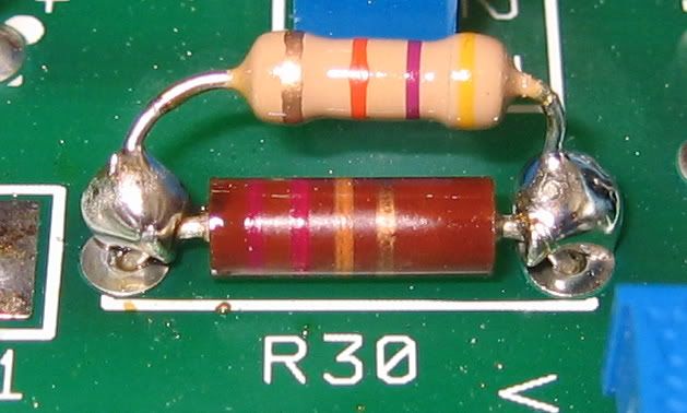
Now what you want to do is locate the R30 resistor. It's right next to the blue bias box with the tiny flat head brass adjustment screw.
What we want to do is solder the ends of the 47K resistor piggy backed onto the R30 resistor. Whether or not my method is the correct one, I use the wire snips to remove most of the excess wire on each end of the resistor and then simply used a small pair of needle nose pliers to form a little J shape hook on each end and hooked them under the R30's side wires that go into the PCB.

If you're wondering, I verified with Scott that orientation of the 47K resistor doesn't matter. Either direction the ends point works.
Once it's in place, simply solder the resistor connections onto the R30.

Not the prettiest picture but hey.. it works.
So now that your solder joints are nice and secure, it's time to fire it up and set the bias!
Go ahead and ensure the standby and power switches are in their off position, plug in the power cord, speaker cabinet and turn the volume knobs all the way down.
Now turn the amp on, let it warm up in standby and then turn the amp on.
Not blown up yet? Good! Time to bias it up!
If you're using the weber bias probe, biasing is easy as pie. Simply plug the positive and negative plugs into your meter, switch the dial to 200m on the dc voltage setting and flip the switch on the little bias probe's switch to cathode current. This will give you a milliamps reading.
The meter will maybe read in the 70.X mA range. Scott recommends an absolute maximum of 60mA.
What we've got here is a decision as to how much of the tube's total plate dissipation you want to utilize. 70% is typically considered the most you should run and will run the tube hotter and shorten it's life. Several techs that know more about this than me that I've spoken with say that a target range of 50~52mA offers the ideal tone and optimal life expectancy.
As mentioned earlier, the bias adjustment screw is on the blue box just next to R30 and has the smaller brass screw.
While still upside down, if the front controls are facing you, turning this screw counter clockwise will lower the cathode voltage down to the range we're wanting to hit so start turning the small screw counter clockwise and after every couple of revolutions, pause to allow the volt meter's reading to stabilize as it will slowly drop.
keep doing this until it reaches the low 50's as this is our target range.
If you don't have the weber bias tool, use this equation to determine the bias.
( Plate voltage X Cathode current ) / 40 (which is the maximum power of a KT88) = the % plate dissipation.
Example: When I had lowered the cathode current to .062 (62 mA)...
(460v X .062) / 40 watts = .7125
So at that point, they're way too hot at 71% max plate dissipation.
First you need to know your plate voltage. From what I've been told (and if I'm wrong let me know), the Nitros have a plate voltage of 460 volts. Whether or not the QR's and other 100 watt splawns also share this voltage, I'm not sure. A quick call to scott could give you a quicker answer than I could as well as how to find the cathode current (which I don't know how to find without the bias probe)
Once you've gotten the plate voltage and cathode current, you can easily use the formula above to pinpoint the exact target cathode current you want to use.
Once you've set it where you want it, you're all done.
Let the tubes cool down and if you're using the bias probe, pull the tube out, remove the probe and then re-insert the tube into the socket.
Then simply work the chassis back into the head shell and re-insert the 4 chassis mounting bolts and reattach the back panel and enjoy the new power!
First thing is first.
You'll need obviously a pair or quartet of matched KT88 power tubes, a voltage meter, a large phillips head screwdriver or drill (to remove the amp from the head shell), a tiny precision flat head screwdriver, a soldering iron and solder, wire snips and last but not least, a 47K 1/2 watt resistor. I got a pack of 6 or so for a dollar at Radio Shack.
Optionally, you can also use a weber bias rite probe to take the guess work out of the biasing procedure. I have the single octal socket with the plate voltage/cathode voltage switch.
After you've got all your stuff, begin by removing the back panel of the amp and remove the 4 screws from the bottom and slide the amp out from the head shell.
First thing you want to do is fire up the soldering iron to get it hot while you prep the amp for surgery. I use the weller variable wattage unit from Sears as it lets me drop the voltage when working with more delicate pieces.
Next!
If you're using the weber probe, insert it into one of the inner 2 sockets and then put a KT88 into it and fill the rest of the sockets with the rest of the tubes. If you're only using 2 KT's just fill the center 2 sockets.

Now that your tubes are in, you can flip the amp upside down and let the side cleats on the inside of the headshell support the metal chassis while you work on it. The tubes should have enough room below to allow the amp to rest without them hitting the surface below. Just lower it slowly and carefully so as not to damage the tubes.
Now what you want to do is locate the R30 resistor. It's right next to the blue bias box with the tiny flat head brass adjustment screw.
What we want to do is solder the ends of the 47K resistor piggy backed onto the R30 resistor. Whether or not my method is the correct one, I use the wire snips to remove most of the excess wire on each end of the resistor and then simply used a small pair of needle nose pliers to form a little J shape hook on each end and hooked them under the R30's side wires that go into the PCB.

If you're wondering, I verified with Scott that orientation of the 47K resistor doesn't matter. Either direction the ends point works.
Once it's in place, simply solder the resistor connections onto the R30.

Not the prettiest picture but hey.. it works.
So now that your solder joints are nice and secure, it's time to fire it up and set the bias!
Go ahead and ensure the standby and power switches are in their off position, plug in the power cord, speaker cabinet and turn the volume knobs all the way down.
Now turn the amp on, let it warm up in standby and then turn the amp on.
Not blown up yet? Good! Time to bias it up!
If you're using the weber bias probe, biasing is easy as pie. Simply plug the positive and negative plugs into your meter, switch the dial to 200m on the dc voltage setting and flip the switch on the little bias probe's switch to cathode current. This will give you a milliamps reading.
The meter will maybe read in the 70.X mA range. Scott recommends an absolute maximum of 60mA.
What we've got here is a decision as to how much of the tube's total plate dissipation you want to utilize. 70% is typically considered the most you should run and will run the tube hotter and shorten it's life. Several techs that know more about this than me that I've spoken with say that a target range of 50~52mA offers the ideal tone and optimal life expectancy.
As mentioned earlier, the bias adjustment screw is on the blue box just next to R30 and has the smaller brass screw.
While still upside down, if the front controls are facing you, turning this screw counter clockwise will lower the cathode voltage down to the range we're wanting to hit so start turning the small screw counter clockwise and after every couple of revolutions, pause to allow the volt meter's reading to stabilize as it will slowly drop.
keep doing this until it reaches the low 50's as this is our target range.
If you don't have the weber bias tool, use this equation to determine the bias.
( Plate voltage X Cathode current ) / 40 (which is the maximum power of a KT88) = the % plate dissipation.
Example: When I had lowered the cathode current to .062 (62 mA)...
(460v X .062) / 40 watts = .7125
So at that point, they're way too hot at 71% max plate dissipation.
First you need to know your plate voltage. From what I've been told (and if I'm wrong let me know), the Nitros have a plate voltage of 460 volts. Whether or not the QR's and other 100 watt splawns also share this voltage, I'm not sure. A quick call to scott could give you a quicker answer than I could as well as how to find the cathode current (which I don't know how to find without the bias probe)
Once you've gotten the plate voltage and cathode current, you can easily use the formula above to pinpoint the exact target cathode current you want to use.
Once you've set it where you want it, you're all done.
Let the tubes cool down and if you're using the bias probe, pull the tube out, remove the probe and then re-insert the tube into the socket.
Then simply work the chassis back into the head shell and re-insert the 4 chassis mounting bolts and reattach the back panel and enjoy the new power!


 ...
... 